Sunday, March 15, 2015

Some other lesson learnt...

After many years fiddling with Arduino, I found (or at least remembered) that "unconnected input pins float randomly between HIGH and LOW state". Thus this rig - and the accompanying sketch "assert a pin and watch if any of other 23 change" - was dismantled because useless (I didn't want to solder 24 pulldown resistors)...


...and then, while writing this blog page, I remembered the INPUT_PULLUP thing. I had to rewrite the sketch as "watch a pullup pin while writing LOW on some of the other 23".

Till today, I was ready to bet that a 24-pin interface for a keyboard had to be some row/column fitting. For example, one row-select pin, six row pins, one column-select pin, 16 column pins. The shown keyboard (a K9405076 produced in 1996) physically has:
- 17 keys on first row
- 14 on second
- 15 on third
- 14 on fourth
- 14 on fifth
- 12 on sixth
for a grand total of 86 keys. The extra physical key on the first row is easily reportable as being part of the second row. I guessed that to read a key, the BIOS scanned every column (write a logical "true" on one, watch for any "row" changed, identify the key combination in a matrix). I only had to figure out the pin numbers (any pin could be row, column or select).

My first attempt was wrong because on the Arduino an "unconnected" input pin floats randomly between high/low states, and the only available Arduino feature for unconnected pins is the INPUT_PULLUP thing. So I had to give a try with a different schema: "for every keyboard pin, set everything Low and check if an High appears somewhere" to identify the column-select or row-select (the former would react on more than six keys). I connected the 24 keyboard pins to the area containing Arduino Mega digital I/O ports from 22 to 51, and started this:
//
//      keytest.ino -- 24 pin keyboard test

void scan()
{
  int n, i;
  for(n=22; n<52; n++)
  {
    for(i=22; i<52; i++)               // set everything low
    {
      pinMode(i, OUTPUT);
      digitalWrite(i, LOW);
    }

    pinMode(n, INPUT_PULLUP);          // examine pin n: "unconnected" --> HIGH
    digitalWrite(n, HIGH);             // enable internal pullup

    if(digitalRead(n)==HIGH) continue; // just ignore unconnected pins

    Serial.print(n);                   // pin n is connected somewhere: announce it
    Serial.print(": ");

    for(i=22; i<52 && i!=n; i++)       // for any remaining output pin:
    {
      digitalWrite(i, HIGH);           // examined pin goes from LOW to HIGH ?
      if(digitalRead(n)==LOW) continue;

      Serial.print(i);                 // yes: announce the connection
      Serial.print(" ");
      digitalWrite(i, LOW);            // set to LOW again to continue checking
    }

    Serial.println();
  }
}


void setup()
{
  Serial.begin(115200);
}


void loop()
{
  scan();
}

I expected it output some numbers when pressing some keys. Alas, on many keys nothing happens, while a few keys (most notably on the right side) only show some pin numbers when pressed in combination of two or three, suggesting that row-select and column-select are the first two keyboard pins starting from keyboard center (the ones with longest vias). I'm currently stuck because I cannot understand if:

  • (1) my FPC to 0.1" adapter thing does not work correctly,
  • or (2) the keyboard is actually broken, maybe in the connector area,
  • or (3) the scheme requires more than a single row-select pin and a single column-select pin.
So I checked again and again the FPC-side connection and tested my adapter - everything is OK.

And then I finally tested the FPC connector keyboard. I wasn't able to verify a single key - this still does not add useful information. I will clean the connector and test again.

Cheap chinese keyboards come for less than five bucks - but, hey!, this project is meant to use the spare parts: buying a thing to replace a non-broken spare part is unacceptable...

Friday, March 13, 2015

Every time you start a project, someone did it better than you two or three years before

While I was drawing a plan like this one for my Emma interpreter/environment:
I stumbled upon the Bitlash project: an interpreted language only requiring some 16 kb code space, useful with as low as 512 bytes RAM, specifically tailored for Arduino hardware.

Just gitcloned it, I'm somewhat curious to see how much ideas I can get for my Emma - or even substitute it with Bitlash (while I would like to use anyway at least a large percentage of the 124k code space of the Arduino Mega).

Thursday, March 12, 2015

A small update

Any personal project starts enthusiastically but in a few days "something happens" and the enthusiasm level goes somewhat down. Geez, in five days I only soldered (in a hurry) the connector thing:


Sometimes I think that one of the most unheard life lessons is how to transform the "short-lived peak enthusiasm" graph into a "decent, constant and non-decreasing" one. Like the MPPT chargers and their wizardry to convert many-volts-few-milliamperes into many milliamperes.

I started this blog only to reminder myself what I am doing, what I've done, how many days passed since last interesting update. I bet geniuses are many more than we could guess - but 95% of them does not end a good project, or does not have time to decently publish it. Thus I started a blog to tell myself "go on!".

I've been featured on Hackaday - only once, and this is my biggest shame. A few days ago I was asked for a CV by a large firm (first time in many years: my DNA is a freelancer type) and I found that I am still unable to fill it with a "portfolio" section of completed projects to show my creativity.

Once again, this morning I decided that Cyprida project must go on. Its main objective is recycling some of my spare parts and telling my friends "When Men Were Men, They Built Their Own Computer, Language and Operating System".

Friday, March 6, 2015

Today's lesson: never underestimate the spare parts drawer

That old and slightly damaged notebook keyboard required a 1mm 24 pin FPC connector. I bought a DIP one (that is: two rows, 12 pins each, pins are 1mm-spaced; the second row has a 1mm offset) for easier soldering.

In my spare parts drawer I just found a 11-pin female-to-female 2mm spare cable (apparently cannibalized from a logic board of a VHS player bought some 30 years ago). I cut it and now have two 11-pin female jumpers: now I only need to solder two pins.
Just placed there to shoot a photo. I'll have to glue or tape them.
Never underestimate the spare parts drawer. But a couple minutes extra on the parts supplier website could have solved even better the "1mm to 1/10inch dilemma".

Anyway, this fits in the "building a portable computer using mostly spare parts" philosophy. Can't wait to get the keyboard up and running...

Thursday, March 5, 2015

A case for Cyprida

A dremelable black case for Cyprida, sufficient to accommodate the keyboard and the display on the largest side. I didn't even test the keyboard yet:


And also a DIP female connector for the 1mm flexible circuit of the keyboard. It will need a bit of work to "convert" those 2mm-spaced pins to a 0.1" pitch connector for the Arduino, but these FPC connectors were the nearest useable thing available (1mm to 0.1" pitch changer boards actually exist, but I would have had to wait 4-6 weeks for shipping; this came instead in 3 days):


Ordered on Monday, I got everything in Thursday morning: three days overseas shipping. Man, I will surely buy again stuff on Mouser.


Saturday, February 28, 2015

"Cyprida 2" already in the works?

While working on the Cyprida project I think about possible enhancements.

While searching for a retroilluminated 4x40 text LCD display I found this one on Futurlec ($44.90, ouch!): apparently its page has an error in the Interface Pin Connections because it only lists a single "E" (enable) pin, while a 4x40 LCD needs two (namely "E1" for the upper 2 lines, and "E2" for the lower 2 lines). And it does not say if the internal font is the Euro/USA one or the Japanese one:


So I started searching for a 320x200 display (320x200 is 64000 pixels with 16:10 aspect ratio), which I consider more interesting than a 320x240 display (76800 pixels and a 4:3 aspect ratio).

Futurlec also has some fancy blue 320x240 graphic display but the price is far from being interesting ($119.90); its controller accepts Seiko SED1335 commands, vaguely resembling Hitachi HD44780 ones, but with more operations about graphics and overlays. Apparently it does not have simple operations like "draw pixel, draw diagonal line", which need to be implemented in the Arduino (at a higher cost). This is because those displays were intended for monitoring data, not for experimenting with graphics or emulating home computers...


Spanish supplier of the Shenzen Topway has a nice 320x200 "green on black" monochrome graphic display. Sadly I can't find the commands list - I guess it is a SED1335-type. No pricing information available (grunt!).


It also features a nice "black on yellow" 4x40 text LCD display:


A very nice 5.7" 320x240 64k-color display is available as well, with a complete firmware (functions like "draw pixel", "draw line", "fill circle" and so on) and even a RS232 port for commands. It would be great to have it on my future "Cyprida 2" project. I am only unable to figure out a price...


Friday, February 27, 2015

Browsing components suppliers websites brings lots of ideas

I was searching Distrelec for a 4x40 LCD display (they don't have it, and their displays are quite expensive), and instead found this case:
I only need to apply something like it on Cyprida's 4x40 LCD display... which has a view area of about 154x28mm and a metallic black border of 173x48mm.

The above product has a 145x28mm window and is 161x40. Oops: too small! The biggest one available is 169x27mm, still too small.

But when I said "too small" i just had a look to my Dremel tool. I may cut my own cover to accomodate the 4x40 display.

I was also searching for some "notebook-sized" rigid plastic box. I found on Mouser this one that seems acceptable (not really on the cheap side) for my Cyprida project:
Its external size is 9.3" x 11.1" x 2.2", that is 236 x 281 x 56mm; I guess that the useful volume is 10mm less on every side. I did not choose a smaller one because I think I may accomodate one or two 5V batteries; I have two somewhat aged MobilePowerPack Li-Ion 5V batteries (USB-chargeable), 13 x 78 x 132mm.

Thursday, February 26, 2015

I need to emulate my own functions

Cyprida has 124 kb EEPROM space for code, way more than the 8 or 16 kb ROM of the home computers of the Legendary Eighties™, when Men were Men and had to fight with limited RAM resources and the twin monsters PEEK & POKE. Thus I will have limited RAM and will only need to implement some cryptic PEEKs & POKEs.

To test features without rewriting the EEPROM every time, I separated the actual Arduino-only code from the interpreter/editor code (which I can run on my PC). Now I have:

- cyprida.ino: sketch that will run on the ArduinoMega. Has a large setup() initializing everything, a library for the its peripherals, and a loop() that only calls emma() to start the interpreter/editor;

- cyprida.h: prototypes for the "emulable" functions (like "clear screen", "print a character", etc)

- ardlib.cpp: emulation of the Arduino functions ("clear screen" and so on): initializes the Linux terminal and then starts emma()

- emma.cpp: the actual environment-interpreter only depending on cyprida.h functions (it is included by both cyprida.ino and ardlib.cpp).


The Makefile builds both the Arduino sketch and an emma executable to test.


Tuesday, February 17, 2015

Bluetooth (via UARTSB-2.2) now works (sort of)

I'm fiddling with my remaining hardware drawer. It was about 2009-2010 when I bought an UART_SB 2.2 on SeeedStudio; don't know why I got it. A little later I bought a solderable Bluetooth Bee and practiced 2mm-pitched hand soldering with a 60 W soldering station!! Arrrgh.

Well, I now have this beast working either as a "USBserial to Bluetooth" adapter for the PC or "TTL serial to Bluetooth" adapter for the Arduino. I spent three entire evenings to figure out a working sequence, and finally was able to print on the LCD of the Arduino Mega a string sent via Bluetooth from Linux PC and getting an answer.


First, it requires a long initialization (ouch!) up to fourteen seconds at boot time before it can accept a connection (while everything other completes in less than 60 milliseconds).

I think this is due to an old firmware release of the soldered BluetoothBee unit. It does not answer "OK" to commands, but a rather clumsy "WORK:SLAVER". So I checked for a capitalized "K" instead of "OK" - it gets both "OK" and "ORK...".

So in my .ino source I wrote a function bluebee(char*) that:
  • waits 120msec
  • sends the command string with Serial3.print
  • reads any incoming characters
  • if a 'K' is received, then flush incoming characters in 30msec and return "OK"
  • if the function is running for more than 3.3 seconds, then call for "FAIL".
And then initialized it on the Arduino Mega using:
  delay(1000);                      // at boot: wait 1sec before sending commands
  bluebee("\r\n+STWMOD=0\r\n");     // 0: client (slave) mode
  bluebee("\r\n+STNA=MyArdu\r\n");  // set bluetooth hostname
  bluebee("\r\n+STAUTO=0\r\n");     // 0: disable "autoconnect last paired device"
  bluebee("\r\n+STOAUT=1\r\n");     // 1: enable paired device to connect
  bluebee("\r\n+STPIN=0000\r\n");   // set a pin to accept incoming connections
  delay(2000);                      // required pause after setting up the pin
  Serial3.print("\r\n+INQ=1\r\n");  // 1: enable inquiring
  delay(2000);                      // required pause after sending the INQ=1

Yes, the +INQ=1 command does not answer anything. Yes, those delays are quite tight, do not reduce them. Yes, I did not use the +STBD to setup baudrate because I was happy with the default 38400; you don't need ultra-turbo speeds to send a few characters at a time.

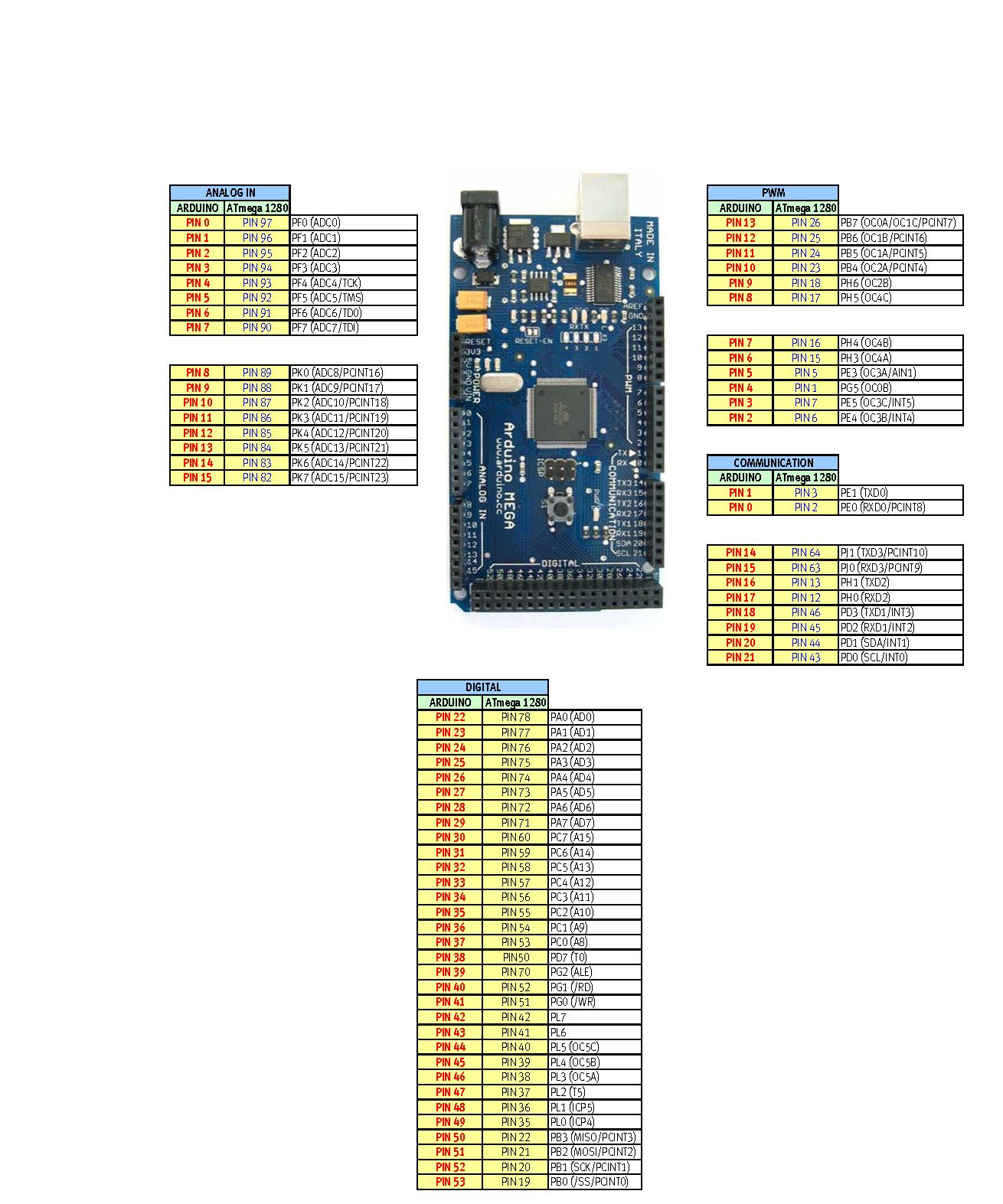
Connections: the TX3/RX3 of the ArduinoMega are connected to the RX/TX pins of the UARTSB (note the mini-dip-switches on "5V" and "Bluetooth"), while the +5V and GND are required on the USB plug side. I cut a miniUSB connector and soldered its red/black (+/-) cables to the 5V/GND pins of the Arduino Mega.

For debugging reasons, I added to the .ino source a loop to print on the LCD of the ArduinoMega the incoming characters of the Serial3 port.


Operation:
  • apply power to turn on the ArduinoMega
  • wait for its boot and bluetooth initialization
  • on the Linux PC bluetooth section, select "Setup (pair) a new device"
  • wait the name to appear in the device list (the above example uses "MyArdu")
  • choose a pin number to pair it (the above example uses 0000)
Yes, the UARTSB+BluetoothBee do not have "memory": on my PC I have to delete the pairing ad redo it again every time the ArduinoMega is rebooted.
If I forget to delete/redo the pairing, the cat /dev/rfcomm0 shown below will silently terminate in about 3.7 seconds because a rebooted BluetoothBee does not "remember" having paired with my PC.
Then release (if already assigned) and create the radiofreq communications channel /dev/rfcomm0 as a serial port (type 1). If you don't remember the fixed address of the BluetoothBee you can use the hcitool scan --flush command to find out after the initialization is completed (in the example below it is 00:18:E4:E5:E6:E7).

  hcitool scan --flush
  sudo rfcomm release 0; sleep 1 ; sudo rfcomm bind 0 00:18:E4:E5:E6:E7 1 

Now if I write something on /dev/rfcomm0 I get a bizarre "Transport endpoint is not connected" error. This is due to the BluetoothBee requiring some time to get a connection up and running.
Note that if you did neither pairing nor rfcomm bind but the /dev/rfcomm0 is still there, you may even get a "no error" on a write... but it will not reach the Arduino.
So I open a terminal window and start cat /dev/rfcomm0 and then in another terminal window I can write using echo ' #OMG it works! ' >/dev/rfcomm0
Trick explained: the cat /dev/rfcomm0 opens the port and stays there waiting for a line of characters. After some time (some five seconds), the BluetoothBee is ready to accept characters.
Note that the Arduino HardwareSerial library has a limited serial buffer - on the Mega it is only 64 characters. This means that if I try to write 70 characters at a time, the entire Bluetooth packet is received by the Bee, then sent to the HardwareSerial library of the Arduino Mega which fills immediately the 64 bytes buffer, losing the extra six characters. The Arduino should continuously consume incoming characters (while(Serial3.available()) { processthisbyte(Serial3.read()); ...) because the 64 bytes buffer will fill in some 16 milliseconds (at 38400 baud speed).

Note: Ubuntu 14.04 Bluetooth Settings has a bug in the "Bluetooth New Device Setup": it forgets the entered pin. So I need first to wait some 10 seconds that the BluetoothBee device appears in its list, then click on it, then click on Pin Options; then select "0000 [most headsets/GPS/etc]" and "Close" the dialog, then click again on the BluetoothBee device in the list, then select again "0000" (most of the times it was "Auto" again) and "Close", and then "Continue". It should not require to enter a six-digit pin...!

Note: when actually "connected", the BluetoothBee name is listed in bold characters in the Settings / Bluetooth window of the Unity Control Center.

Note: one I got you may try to use /dev/rfcomm1 if you think that rfcomm0 is stuck

Yes, this old BluetoothBee has its drawbacks but it works:
  • ArduinoMega has the UART_SB + BluetoothBee ready to accept a "secure" wireless serial channel ("secure" means that you use a non-trivial pin like 0000... but only setup it after you are sure that everything works with the default 0000), that I placed on the TX3/RX3 (because I don't want to fiddle with pins 0/1 TX/RX unless absolutely required); you may consider the SoftwareSerial if you don't have a Mega;
  • once established a connection, ArduinoMega can regularly read incoming characters using Serial.available and Serial3.read and then answer with Serial.write functions
  • on the PC side, it is required to pair again, then release/bind the port, and then open the connection and wait a little while before sending characters.
The above examples use cat and echo but once the serial wireless channel is established, I can work out multiple interrogations. I used a thread for a fake "open channel to read" (to emulate the cat) that gets killed as soon as the main task is "go": here is the rubytalkswitharduino.rb script:

#!/usr/bin/env ruby

fake = Thread.new do
  fpfake = File.open '/dev/rfcomm0'
  while true
    fpfake.gets
  end
end

ok = Thread.new do
  sleep 5
  fp = File.open '/dev/rfcomm0', 'w+'
  Thread.kill fake

  fp.puts " [Ruby: #{$$} OK] "
  puts "PID #{$$} talked; response:"
  puts fp.gets

  fp.puts " <#OMG: #{Time.now}> "
  while true
    print fp.read(1)
  end
end

ok.join

Note that the gets requires a newline (then Serial3.println on the Arduino side). Note also that the gets in the fake thread does not have to get actual data (it just has to stay there waiting for the rfchannel to warm-up). My ArduinoMega just answered to "OK" and "OMG" commands sending (Serial3.println) some text.

Below, the complete sequence script (note that the "sleep 30" was to be sure that some time passed after last "rfcomm release 0"):

sleep 30
sudo rfcomm bind 0 00:18:E4:E5:E6:E7 1
sleep 1
ruby ./rubytalkswitharduino.rb

Sunday, February 15, 2015

Direct 5V supply: just add a diode...

Arduino documentation states that you should not bypass its regulator to supply power - i.e.: don't supply 5V on the 5V pin.


I just read that you can bypass the onboard regulator - just add a diode from 5V (anode) to Vin (cathode) to avoid reverse driving the regulator; for example an 1N4001.

Current through a diode can only flow from the anode to the cathode. Usually diodes have a black or gray line near the cathode.

LEDs: "light emitting diodes":

Saturday, February 14, 2015

What about Arduino Due ?

Arduino Due is a 3.3V board having almost the same pin layout of the Arduino Mega.

Its ugliest drawback is that its input pins are not 5V-tolerant. If you "write" a logical 1 on a higher-rated voltage input pin, it will almost always work ("writing" 3.3V on a 5V input is safe because it is somewhat near 65-66% of the required voltage; I expect it to be catched as a logical 1 everytime; "getting" 5V on a 3.3V-rated input pin means that you probably just destroyed it - or the entire board).


Specifications are quite interesting:

- 96 kb RAM vs. 8 kb RAM: you can emulate a full "64k RAM" 8-bit era computer with 32k extra for the operating system;

- 84 MHz clocked SAM3 processor: you can emulate a full 8-bit era computer at native speed... or way faster;

- 512k flash memory: you can store not only the full emulation program, but also some "floppy disks / microdrive cartridges / tapes" as well;

- the 3.3V rail can supply 800mA current: you can add peripherals and even a small screen requiring up to 2.6 watts total.

Yes, if it had 5V-tolerant I/O pins, it would have been a great machine.

Thursday, February 12, 2015

Cyprida gets gigabytes

Arrrgh. I have slightly more than six kilobytes RAM available, and the smallest microSD card I found in my spare parts drawer is a 4Gib one, featuring 3.8 millions kilobytes free space.


The Arduino SD library uses 512 bytes of RAM to store an entire sector and some extra RAM; serial ports libraries and printf stuff also suck some memory: this is why the free RAM of the ATmega dropped from 8k to about 6600 bytes. I bet the largest block available should be a bit less than six kilobytes.

Current status:
  • 4x40 display: works, but I was unable to do anything more than 7-bit text. I tried to build custom characters but it just didn't work, even in the lower half display
  • piezo beeper: works
  • microSD: works
It's almost time to work out a keyboard.

Next step will be implementing some BASIC interpreter. Man, I hate BASIC, but now I can't figure anything better. A Forth interpreter is just lame; a Pascal interpreter seems useles; a C interpreter could be too complex. I also hate prehistoric stuff like COMIT, Algol, SNOBOL and exotic stuff like Logo, PL/M, REXX.

Well, I'll have to design my own interpreter and editor. It should have the same basic features of a common home-computer of the 80's: execute commands directly or after editing a program listing, easy to learn and use, integers, floats and strings operations, no baroque features, no Commodore PEEK/POKE-bloat.

Tuesday, February 10, 2015

Cyprida gets music


A while ago I bought a buzzer because I read the Arduino Tone tutorial. And now the buzzer is in. I soldered it below the shield to sack some of that unused physical space while hiding that ugly cylindrical chunk (above I placed a 180 ohm resistor, which should limit to some 27mA at 5V; the 180ohm is the only one reasonably near 100 ohm I found in my drawer). I soldered the resistor between the "+" of the buzzer and the pin 10 of the Arduino Mega (it is a PWM enabled one and it is in the zapped zone: I had to wipe out pins 8, 11, 12 and 13 of the dremeled microSD shield because the SPI pins on the Mega are 50, 51, 52 and 53).

I also found a nice project Arduino Music featuring up to six voices on an Arduino Mega. It would require six resistors (as current limiters), having a grand total "parallel resistors" value around 100-150 ohm (I should check how much current the output pins can source, and how much current the buzzer can handle); I bet that different values could get different voice levels. The drawback is that it requires up to all six ATmeg1280 timers and interrupt vectors. No, I don't want to fight with resistors and timers all at once; I'm not building a squarewave 6-voice music machine.

And finally I updated the firmware: a 100msec beep at boot time; 14.5k code space used, only to initialize screen, beep, serial ports and microSD. I wonder how much space I'll have for the actual firmware...

Sunday, February 8, 2015

Drrrremel!

It happened a number of times. Once while talking about cutting pie slices. Another while talking about a small hole. I accidentally used the term dremeling, making people around - mostly girls - asking me: "what?".

Today - a rainy Sunday - a bit of quick and dirty dremeling saved my day. Now I can start soldering some bits. Geez, I can't count the times I said how worthy were those 100+ bucks for a Dremel 4000 set.


Saturday, February 7, 2015

Planning a new contraption

A while ago I bought this Arduino microSD shield and quickly soldered the pins... and a microsecond later my project had to be scrapped.

Sadly, this nice shield uses pins 8,11,12,13, whereas the Mega uses the 50,51,52,53.


Either I de-solder the four pins out there, or I find another way to add a microSD to my Arduino Mega...

Friday, February 6, 2015

Arduino reset serial issue

Today's lesson: experimenting with some serial stuff (*) I saw Arduino Mega rebooting... Welcome to the Infamous Reset Issue. Gotta find a "120 ohm" resistor (that is: compose some resistors to get a value between 110 and 124 ohm).


More info on the Arduino Playground.

(*) it only was Serial3.begin(115200); Serial3.print("test");

Thursday, February 5, 2015

Murphy's Law about 4x40 LCD displays

Well, the 4x40 LCD display is sick - Murphy's law about a project states that while you move your first steps you find some devastating problem, enough to kill more the project value than the project feasibility.

I bought this "untested 4x40 LCD display, should work" at a HAM-fair in Pescara, Italy, some 7-8 years ago, "too cheap to not to buy". And now - only now - I understand why it was so dirt cheap.

It is a 40466 revision 2, based on HD44100FS and HD44780A00 chips (thus the Japanese font version). And now I also notice that manufacturing date on the right side: March 29, 1996.

And it has problems:


It has a number of hardware/software problems, most of all:

1) does not work correctly with any of the Arduino LiquidCrystal libraries (including Extended, 4x40, etc), many commands either do not work or just crash;

2) it has a large area (from the 3rd to the 34th character cell of the first two lines) that is not correctly drawn (apparently the vertical control lines are shifted). No, the font commands did not change the result.

So I began to write my own display driver from scratch using the HD44780 documentation.

After some experimenting I found a few reliably working bits:
- a screen initialization sequence
- the "move cursor" instruction
- the "print a character" instruction
- the "show/dontshow cursor" function.

This is sufficient to make it work. For example, I had to implement a clear screen function moving cursors to home and printing 80 blank spaces, because the LCD clear screen command does not work. I had to implement a memory map and a "known last cursor position" thing as well. But -hey!- it now works, including backspace, tab, scroll, and a single flashing cursor (yes, normaly it shows two cursors! 4x40 displays are actually two 4x20 in a single case).

A minimal Hello World program only requires 1676 bytes of flash space.

Monday, February 2, 2015

Why Arduino Mega?

I have a spare Arduino Mega 1280. I bought it years ago, only to complete my collection of Arduino boards. I started the current project only to have it doing more than blinking a LED. And I found some interesting features.

First, it has lots of directly addressable pins... grouped together. For example, to set to "high" the pins marked "analog pins 0 to 7" as GPIO (digital pins), it is sufficient a single instruction:
PORTF = 0xff;
It is also convenient for setting more than one pin in a single instruction:
PORTF &= 0x3c;
More info on Port Manipulation.


Summary on the Arduino Mega boards (1280 and 2560):
  • PORTF: 8 in-line pins, west side ("analog pins 0 to 7")
  • PORTK: 8 in-line pins, west side ("analog pins 8 to 15")
  • PORTA: 8 pins (two adjacent rows of 4 pins), south side ("digital pins 22 to 29")
  • PORTC: 8 pins (two adjacent rows of 4 pins), south side ("digital pins 30 to 37")
  • PORTL: 8 pins (two adjacent rows of 4 pins), south side ("digital pins 42 to 49")
  • note also the blocks of 4 adjacent pins for PORTB, PORTH, PORTD.
If you don't need analog pins, you can fully use PORTF and PORTK to read/write up to eight pins at a time.

If you don't need external RAM/SRAM, you can fully use PORTA and PORTC.

If you don't use weird things like external interrupts, you can fully use PORTL.

Yeah, five blocks of 8 pins each. Things like:
if(PINK) call_a_function();
"if any input pin of PORTK is on level high, then call a function".

Just forget the digitalRead/digitalWrite stuff.

Just don't forget to assign the appropriate data direction register in the setup() phase.
DDRF = 0xff;    // declare eight output pins
PORTF = 0x1f;   // output 3 low and 5 high pins

Sunday, February 1, 2015

Many pins, easy keyboard

Having many I/O pins directly addressable means that you can immediately scan a keyboard.

Example: an intercom numeric keyboard, 4 rows by 4 columns (16 keys total):


it has 8 pins (4 for rows, 4 for columns): when you press a key, their respective pins are shorted.


Imagine you have those 8 pins on a single port of the Arduino, for example PORTC and its data direction register DDRC. You don't have to use digitalRead, you just read and write PORTC value, sending '1' to all columns to check if any row has changed, and vice-versa. For example:

int keypressed()
{
  // start with first scan: high bits (columns)
  DDRC  = B11110000;
  PORTC = B11110000;
  int c = PINC & B00001111;
  if(c == 0) return 0;  // return if "no key pressed"

  // a key was pressed, and now we know the columns
  // now: second scan: low bits (rows)
  DDRC  = B00001111;
  PORTC = B00001111;
  int r = PINC & 0xf0;
  if(r == 0) return -1;  // return "unknown" if key was released before this point

  switch(c | r)
  {
    case B10001000: return '1';
    case B10000100: return '2';
    case B10000010: return '3';
    case B10000001: return '4';
    case B01001000: return '5';
    case B01000100: return '6';
    case B01000010: return '7';
    case B01000001: return '8';
    case B00101000: return '9';
    case B00100100: return '0';
    case B00100010: return 'z';   // "lamp" key
    case B00100001: return 'u';   // "phone" key
    case B00011000: return '#';
    case B00010100: return '*';
    case B00010010: return 'k';   // "key" key
    case B00010001: return '\n';  // "return" key
  }

  return -1;  // return "unknown" if more than one key pressed
}


Code needs a bit of extra to check for key-released event and bouncing; it may be easily optimized using a look-up table, and some extra code could identify combinations of keys (e.g. for things like "shift-" or "ctrl-").

Saturday, January 31, 2015

About the keyboard

A good name for this project could be: "I have some spare hardware and did not yet start a project using it":
  • Arduino Mega 1280
  • 4x40 LCD display, requiring 3+8 GPIOs (digital pins)
  • 12-keys physical keyboard, requiring 4+4 GPIOs
  • full-blown notebook keyboard, with a FPC 24 connector (24 GPIOs)
The full keyboard only has a flex parallel cable (24 pins with 1mm spacing), thus requiring a connector. This is my first time fiddling with 1mm-spaced things, but I decided to go with it because having a full keyboard opens a wide range of applications.

Note: this is a FPC 12P 1mm-spaced

I'm considering a Würth Elektronik FFC/FPC 24P connector (€2.60 on Distrelec). After quite a bit of googling, I didn't find anything easier to solder manually (pitch changers 0.1mm to 0.1" do exist but I can't find a FPC-female-to-0.1"-spaced-male connector).

I will search again other shops (Mouser, RS components, Farnell, etc) because I don't want to spend 10 bucks local shipping for a 2.60 bucks component...

Friday, January 30, 2015

RAM considerations

The ATmega1280/2560 have 8 kilobytes internal RAM; some digital pins (PORTA/PORTC, PORTD bit 7 and PORTG bits 0 to 2) may take avantage of a RAM/SRAM chip on the 0x2200-0xffff addresses, and even switching between 8 banks (up to 8x64k RAM).

Note 1: the initial 0x0000-0x2200 area (8704 bytes) is not available because the internal RAM has precedence over external RAM.

Note 2: a 5V RAM is needed because the ArduinoMega is 5V.

Note 3: the RAM should feature 60ns or lower access time, because the ATmega is clocked at 16 MHz.

Cypress CY7C199CN pinout

I could add 32k SRAM and map it from 0x8000-0xffff. But... hey, 512k is cheaper than 32k! Some examples:
  • Cypress CY7C199CN-15PXC, 32 kilobytes SRAM (32 kbits x 8 = 256 kilobits), PDIP package (0.1"-spaced, easy to solder), 15ns speed; Farnell lists at €5.67 each;
  • BSI BS62LV1027PCP55, 64 kilobytes DRAM (64 kbits x 8 = 512 kilobits), PDIP, 55ns speed; Distrelec lists at €6.60 each;
  • Alliance AS7C4096A-12JCN, 512 kilobytes SRAM (512 kbits x 8 = 4 Mbits), PDIP, 12ns; Mouser has them at €4.50 each (yes, cheaper than the 32k above).

Thursday, January 29, 2015

Grappendorf!

Every time you start a project, you find on Hackaday someone that made one better than yours on every aspect.

Enter the Grappendorf computer - 6502 based, 4x40 white-on-blue display, 32k RAM, full keyboard, 3D-printed case, custom PCBs and a lot of extra goodies:


Most important lesson learnt from his project: a 5 bucks USB keyboard could be cheaper than adapting an old notebook keyboard. Recycling parts could be quite expensive.

Second lesson learnt: now I really *want* a 3D-printer!!! :)

Wednesday, January 28, 2015

Hardware - preliminary


keyboard: this full-blown notebook keyboard has a 24 pin 1mm-spaced flexible connector. Varitronix display and Arduino Mega shown for size comparison.

Tuesday, January 27, 2015

Welcome to CYPRIDA project

CYPRIDA computer main specifications:


motherboard: Arduino Mega 1280
  • CPU: 32-bit ATmega1280 @ 16 MHz
  • RAM: 8 kb
  • Flash: 128 kb (operating system)
  • EEPROM: 4 kb (configuration)
  • GPIO: 54 digital + 16 analog pins, including SPI, I2C, four TTL serial ports and 6 external interrupts


display: Varitronix MDLS-40466

  • type: 40x4 alphanumeric LCD
  • interface: classic 8-bit HD44780 (14 pins)
  • size: 196x56 mm